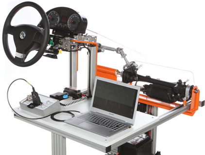
Electromechanical Power Steering Trainer
In this functional model of an original electromechanical power steering the components are exposed within the steering housing in order to demonstrate for example the operation of the double drive pinion. Because of the extremely high forces on all moving parts and rotating the open areas were fitted with transparent covers for safety. More representable functions are active reset in the directional stability as well as the controlled demand for power consumption for reduction in fuel consumption. The communication between the control unit for steering column electronics, the diagnostic interface (gateway) and the Diagnostic Interface (OBD) is done via CAN Bus.
Steering angle, power consumption and torque can be tested and measured using standard workshop diagnostic systems via the OBD interface. In order to increase the steering forces partially, a resistance pressure box is mounted. Thus, the required effort with and without assistance can be represented visually. The system has a control panel with emergency stop switch, ignition switch, indicator light and OBD interface. The power supply is provided by a
vehicle battery. Including error circuit 6 switches / 12 errors and associated test sockets (pin-outs) in 4mm design.

- Design of an electromechanical power steering
- Function of the individual assembly groups
- Steering geometry
- Inverter control
- CAN bus control
- Steering angle sensor
- Steering moment sensor
Product: Electromechanical Power Steering Trainer
Product Code: ELPS-001

